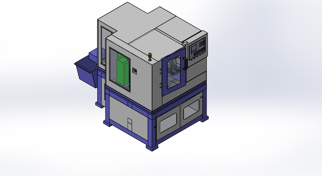
Machine will be fabricated by rigid, Stress relived and fabricated structure
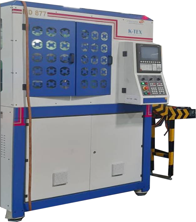
Top of the base and center of the machine servo driven rotary table mounted, it’s divided into 10 stations
The fixture designed by component Reference location pin and Id Location, job clamped by manual clamp
Component having 11 number of M4 Tap operation, based on CD and PCD, we divided into no of drilling and tapping heads
Station 1 – Loading station – Manual Load component and manual clamp
Station 2 – Multi head drilling station – this station having 4 numbers, Diameter 3.3 mm drill mounted on it with Guide bush arrangement, this drill head unit moment by vertical hydro pneumatic Feed control, drill Spindle run by 0.5 hp induction motor and driven by V belt arrangement.
Station 3 – Multi head tapping station – this station having 4 numbers, M4 Tap mounted on it, this tap head unit moment Pitch control lead screw arrangement, drill Spindle run by 0.5 hp induction motor and driven by V belt arrangement.
Station 4 – Multi head drilling station – this station having 2 numbers, Diameter 3.3 mm drill mounted on it with Guide bush arrangement, this drill head unit moment by vertical hydro pneumatic Feed control, drill Spindle run by 0.5 hp induction motor and driven by V belt arrangement.
Station 5 – Multi head tapping station – this station having 2 numbers, M4 Tap mounted on it, this tap head unit moment Pitch control lead screw arrangement, drill Spindle run by 0.5 hp induction motor and driven by V belt arrangement.
Station 6 – Multi head drilling station – this station having 3 numbers, Diameter 3.3 mm drill mounted on it with Guide bush arrangement, this drill head unit moment by vertical hydro pneumatic Feed control, drill Spindle run by 0.5 hp induction motor and driven by V belt arrangement.
Station 7 – Multi head tapping station – this station having 3 numbers, M4 Tap mounted on it, this tap head unit moment Pitch control lead screw arrangement, drill Spindle run by 0.5 hp induction motor and driven by V belt arrangement.
Station 8 – Multi head drilling station – this station having 2 numbers, Diameter 3.3 mm drill mounted on it with Guide bush arrangement, this drill head unit moment by vertical hydro pneumatic Feed control, drill Spindle run by 0.5 hp induction motor and driven by V belt arrangement.
Station 9 – Multi head tapping station – this station having 2 numbers, M4 Tap mounted on it, this tap head unit moment Pitch control lead screw arrangement, drill Spindle run by 0.5 hp induction motor and driven by V belt arrangement.
Station 10 – Unload station
Total Machine controlled by Servo system, PLC and HMI
Each Drilling station given read switch for position control
Each Tapping Station given Proximity sensor for Position control
Machine given Manual Centralized lubrication given all drilling and tapping heads
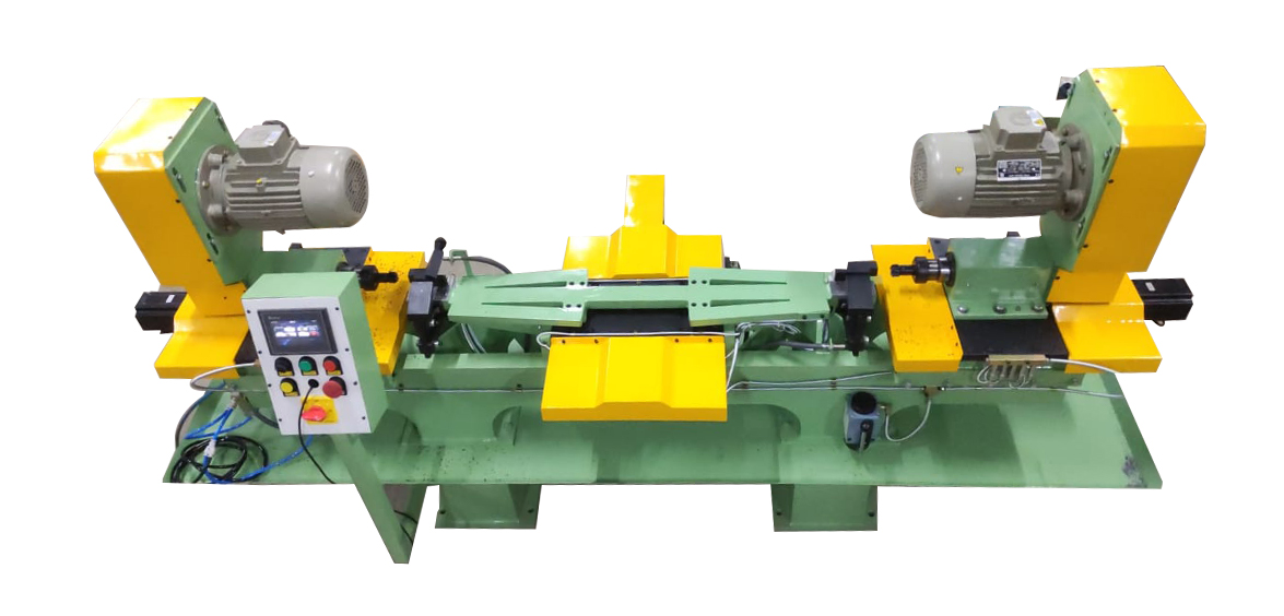
Top of the base constructed a slide moment Carriage arrangement
Slide moment made by LM Guide ways and Ball Screw arrangement, carriage stroke moment 500.0 mm
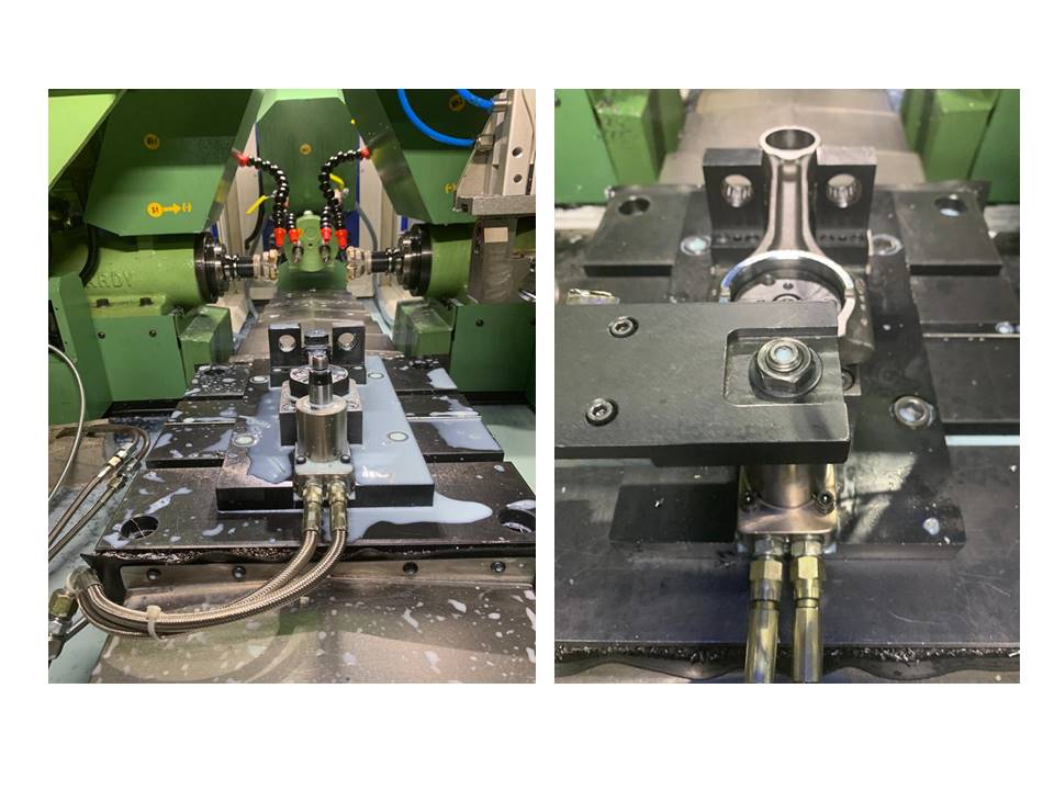
The fixture designed by component Reference location and full proof, job clamped by manual toggle clamp on either side, this fixture setup mounted above the carriage.
Multi Drilling and tapping spindle head mounted above the base on either side (RH side Multi Drill spindle head / LH side Multi Tapping Head)
Multi drill spindle head having ER11 Collet
Multi tapping Spindle Suitable for TR16 Tapping Adaptor
Carriage Slide moment run by servo motor
Multi head drilling station – this station having 2 numbers, Diameter 2.5 mm drill mounted on it with Guide bush arrangement, this drill head unit moment by vertical hydro pneumatic Feed control, drill Spindle run by 0.5 hp inductions motor and driven by V belt arrangement.
Multi head tapping station – this station having 2 numbers, M3 Tap mounted on it, this tap head unit moment Pitch control lead screw arrangement, drill Spindle run by 0.5 hp induction motor and driven by V belt arrangement.
Total Machine controlled by Servo system, PLC and HMI
Touch panel given for Operator parameter setting of Position and Feed rate
Each Drilling station given read switch for position control
Each Tapping Station given Proximity sensor for Position control
Multi spindle head having easy changing arrangement of different jobs
Machine given Manual Centralized lubrication given for axis guide ways, Ball screw nut and all drilling and tapping heads
A slide moment run by Stepper motor with PLC System
Above the Y-axis Bed job Clamping Fixture setup mounted and Job Clamp by Pneumatic Toggle Clamping to the both the ends with manual job reference stopper
Manual Component Loader
Job Reference stopper release Confirmation
Job Clamp Confirmation
Pendent for operator
Touch Panel given for Component offset setting, Position, Feed rate Parameters settings and tool compensation settings.

")
")
")
")
")

")
")
")
")
")
")
")